In this page, we will learn how to set boundary conditions (B.C.) for simulations so that you can set up your own simulation from scratch. However, you are recommended to find a similar case from Sample Problems, and modify its input files (bc.bmp, grid.txt, etc.) to suit your case.
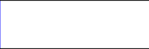
Boundary conditions are important since it determines the solution on the boundaries which propagate throughout the domain. In Flowsquare, we use bc.bmp to define B.C. for simulations, and bc.bmp needs to be prepared for each simulation. In order to set B.C., we can use a usual paint tool such as Microsoft Paint and save the image as *.bmp. For example, the default bc.bmp used for the 2D channel flow simulation is something like this:
The figure represents the boundary conditions in the entire simulation domain. The size of bc.bmp should be the same as the domain size (nx x ny pixels, where nx and ny are specified in grid.txt), although if the size of bc.bmp does not match to the domain size, Flowsquare interpolates the figure for your simulation automatically. Here, you see a blue line on the left side of the domain, and two black lines on the top and bottom of the domain. Each colour has a specific meaning and following colours are used to specify various B.C. in Flowsquare.
- Color (R,G,B): description of B.C. type.
- █ Black (0,0,0): Non-slip zero-flux/fixed temperature boundary (wall).
- █ Blue (0,0,255): Inflow boundary.
- █ Red (255,0,0): Inflow boundary.
- █ Green (0,255,0): Moving wall boundary (zero-flux/fixed temperature).
- █ Pink (255,0,255): Pure air flow (can be used in premixed mode only).
- █ Yellow (255,255,0): Additional scalar boundary.
Specifically for Blue, Red and Pink boundaries, they can be set only on the edge of the entire computational domain (eg. on (i, j)=(1, j), (nx, j), (i, 1), (i, ny) ). If these boundaries are used inside the domain (2<=i<=nx, and 2<=j<=ny), these colours are considered as initial conditions (note initial condition set using bc.bmp is prioritised over by ic.bmp). For each boundary type, there are several parameters to be set in grid.txt. Some parameters are optional so not all of them are to be specified by users. Here is what user will specify for each B.C. in grid.txt. The names of variables actually used in grid.txt are also introduced here. The cmode used in the below is mode of simulation which is 0: non-reactive, 1: reactive (premixed), 2: reactive (non-premixed) or 3: Sub/supersonic set in grid.txt.
- █ Black (0,0,0): Non-slip zero-flux/fixed temperature boundary (wall).
tempew: Temperature on the wall (optional). If it’s set to be the value other than 0 (zero), the wall temperature is fixed during the entire simulation. If it’s set to be 0 (zero), the wall temperature changes depending on the surrounding fluids (generally zero gradient). - █ Blue (0,0,255): Inflow boundary.
uin1: Velocity component in x (horizontal) direction on the boundary.
vin1: Velocity component in y (vertical) direction on the boundary.
rho1: Density on the boundary (has to be set for cmode=0 and 3, if this B.C. is used).
temp1: Temperature on the boundary (has to be set for cmode=1 and 2, if this B.C. is used).
scalar1: Mixture fraction (has to be set for cmode=2, if this B.C. is used). - █ Red (255,0,0): Inflow boundary.
uin2: Velocity component in x (horizontal) direction on the boundary.
vin2: Velocity component in y (vertical) direction on the boundary.
rho2: Density on the boundary (has to be set for cmode=0 and 3, if this B.C. is used).
temp2: Temperature on the boundary (has to be set for cmode=1 and 2, if this B.C. is used).
scalar2: Mixture fraction (has to be set for cmode=2, if this B.C. is used). - █ Green (0,255,0): Moving wall boundary (iso-thermal/fixed temperature).
imb: If it’s set to be 1, the boundary movement is repeated periodically. Set it to 0 (zero) otherwise.
umb: Wall displacement speed in x (horizontal) direction.
vmb: Wall displacement speed in y (vertical) direction.
tempmb: Temperature of the moving wall. If it’s set to be the value other than 0 (zero), the wall temperature is fixed during the entire simulation. If it’s set to be 0 (zero), the wall temperature changes depending on the surrounding fluids (generally zero gradient). - █ Pink (255,0,255): Pure air flow (can be used in premixed mode only).
uin3: Velocity component in x (horizontal) direction on the boundary.
vin3: Velocity component in y (vertical) direction on the boundary.
temp3: Temperature on the boundary (has to be set if this B.C. is used). - █ Yellow (255,255,0): Additional scalar boundary.
scalarT: Scalar value on the boundary (corresponding to c in Eq. (25) without reaction in the Users’ Guide).
It’s always easier to have a look at various example cases in Sample Problems to learn how to use each boundary condition to achieve what you want!
