http://flowsquare.com/upenn/
Design Project — CFD
-
Some explanation on the input files.
- Lesson 2.1 — bc.bmp
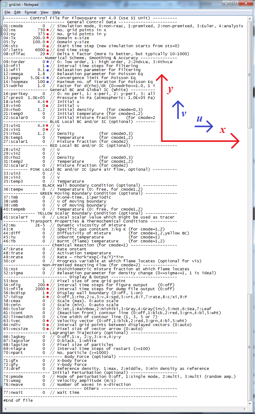
- Lesson 2.3 — grid.txt
- Use SI units
Length: m
Time: s
Velocity: m/s
… - Prepare control file
Typical control file (grid.txt) for UPenn’s design project
Red marks: Basic
Blue marks: Advanced
- Make your simulation case as small as possible
One pixel of bc.bmp = spatial resolution
Example. nx=750 and lx=200 → spatial resolution = 200/(750-1) = 0.27 (m)
Cases
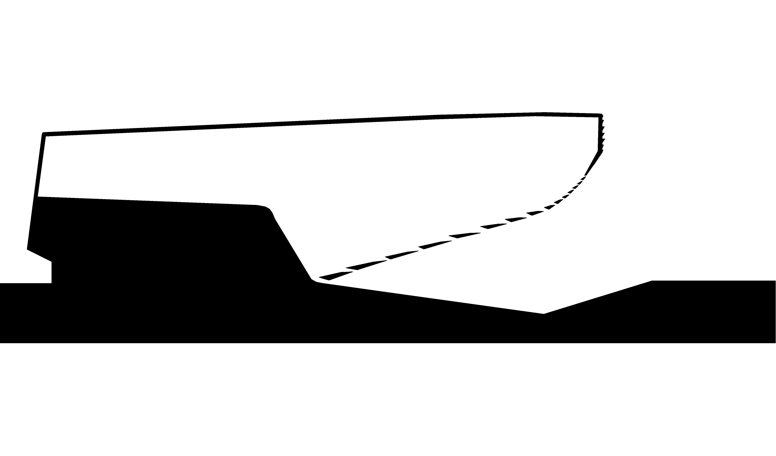
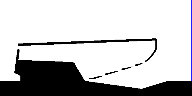
- Group 1 (Control file: grid.txt, Sample result: Nick.html)
Changes:
- Pixel size: 3287×928 → 750×375
- Colour: Wall B.C. → Black (RGB: 0, 0, 0)
- Inflow Boundary: Blue line (RGB: 0, 0, 255) on left side.
- Wall B.C. should be thicker than 3 pixels.
- Additional space between uppper outflow B.C. and top of the object.
- Group 2 (Control file: grid.txt, Sample result: Brian.html)
Changes:
- Pixel size: 2552×1500 → 640×320
- Inflow Boundary: Blue line (RGB: 0, 0, 255) on the right side.
- Wall B.C. should be thicker than 3 pixels.
- Size of the slits (and number accordingly).
- Additional outflow section on the left of the building.
- Assumed the domain size to be 100 (m) x50 (m).
- Assumed the inflow velocity to be 5 (m/s) from left to right.